Mapping an E-R Model to a Relational
Model
An E-R diagram can be converted to a
relational model fairly easy.
1 Transform all relationships difficult to
represent in the relational model.
1.1 Replace all M: M
relationships
Replace all relationships
of M: M type by a weak entity and two relationships. The new relationships will be of type 1:M with the M on the branch to the weak
entity.
Example: Lets consider the
relationship VISIT (Property_for_Rent, Client)
presented in Figure1.
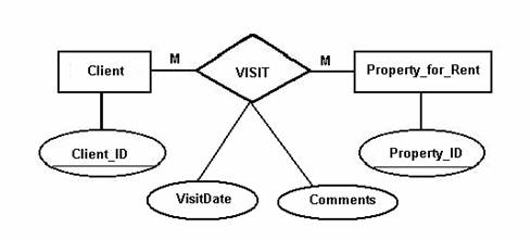
Figure 1
We will
replace it by the diagram presented in Figure 2.
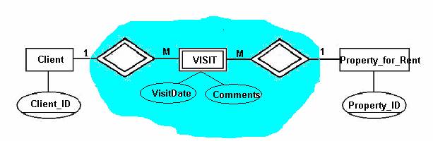
Figure 2
1.2 Replace all recursive
relationships
A recursive
relationship is a relationship between an entity E1 and itself (E1). We will replace the relationship by a weak entity
and two relationships. It is important in this case always to give a name for
each branch of the recursive relationship.
Example: The relationship SUPERVISES presented in
Figure 3 is recursive. We present in Figure 4 its transformation.
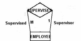
Figure 3
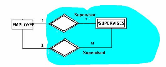
Figure 4
1.3 Replace all relationships having attributes
Replace the
relationship R with attribute A by a weak entity and two relationships. The attribute A will be linked to the weak
entity.
Example: We will
replace the relationship R with attribute A in Figure 5 by the weak entity R
with attribute A and two relationships R1, R2 as in Figure 6.
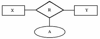
Figure 5
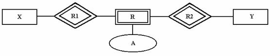
Figure 6
2 The strong
entity represented by rectangles become relations represented by tables.
The table name is the same
as the entity name. The simple
attributes of the entity become attributes of the relation, or column headings
for the table. The primary key of the
entity become the primary key of the table.
For the composite attributes
we will make a column for each of the simple attributes that form the
composite, or we can choose to leave the composite as a single attribute. Multivalued
attributes will be removed from the table and we will create a separate
relation in which we put the primary key of the entity, along with the
multivalued attribute. The key of this
new table will be the combination of the key of the original table and the
multivalued attribute. If there are
multiple multivalued attributes in the original table, we have to create a new
table for each one.
Example:
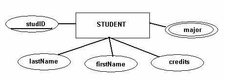
The tables created in
relational model are: STUDENT (studID, lastName, firstName, credits) and
STUDMAJOR (studID, major)
3 We will use foreign keys to map the 1 :1
or 1 :M binary relationships (not versus a weak entity) to the relational
model
·
relationship
1 :1 We will add a copy of the primary key of one
entity into the table corresponding to the other entity.
Example: The relationship R1 may be mapped in two ways
to relational model.
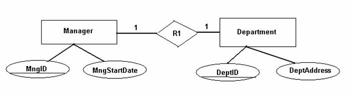
Manager (MngID, MngStartDate, DeptID)
Primary key MngID
Foreign key DeptID reference Department (DeptID)
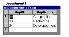
Department (DeptID, DeptAddress)
Primary key DeptID
OR
Manager (MngID, MngStartDate)
Primary key MngID
Department (DeptID, DeptAddress, MngID)
Primary key DeptID
Foreign key MngID reference Manager (MngID)
·
relationship
1 : M, a
copy of the primary key of the entity on the 1 side will be added to the table
corresponding to the entity on the M side, as foreign key.
Example: Tables MEMBER and HORSE
in Figure 8 map the entities MEMBER and HORSE in Figure 7.
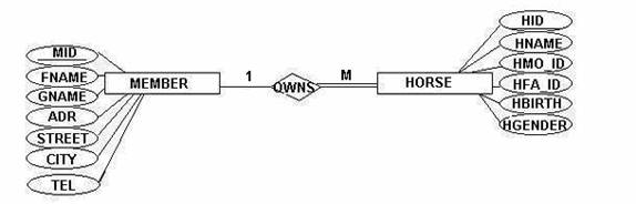
Figure 7.
MEMBER (MID, FNAME, GNAME, ADR, CITY, TEL)
Primary
key MID
HORSE (HID, HNAME, HFA_ID, HMO_ID, HBIRTH, HGENDER, MID)
Primary
key HID
Foreign
key MID reference MEMBER(MID)
Figure 8
4 For each weak
entity map a table with the same name in the relational model.
Add in this table the primary key of all
entities in relationship with the weak entity (as foreign keys) and all the
attributes linked to the weak entity.
For each relationship to or from a weak entity do nothing. The relationship is already represented by
the primary key included in the table corresponding to the weak entity.
Example: The
entities and relationships in Figure 9 are mapped in the relational model by
tables VISIT, Client, Property_for_Rent, CV, VP
(Figure 10).
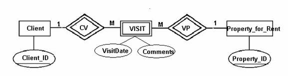
Figure
9
VISIT (ClientID, PropertyID, VisitDate,
Comments)
Primary key
(ClientID,
PropertyID, VisitDate)
Foreign key ClientID reference Client(ClientID)
Foreign key
Property_ID reference Property_for_Rent (Property_ID)
Client(Client_ID)
Primary key Client_ID
Property_for_Rent(Property_ID)
Primary key
Property_ID
Figure 10.
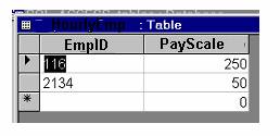
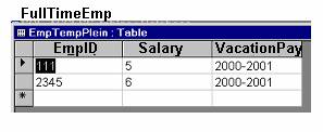
5 How do you map a specialization E-R diagram to a
relational model?
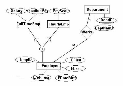
![]()
|
HourlyEmp
|
|
- How do you map a ternary or n-ary relationship on the
relational model?
You
construct a table for the relationship, in which you place the primary keys of
the related entities. If the ternary or n-ary
relationship has attributes, they go in the relationship table.
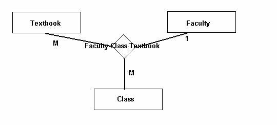
For one
Faculty instance and one Class instance there are one or many Textbooks. For one Class instance and one Book instance
there is one single faculty instance.
For one Faculty instance and one Textbook instance there are one to many
Class instances. The FacID
is unique for each instance of the pair (TextID, ClassID).
The
corresponding table in the relational model is:
Faculty_Class_Textbook(TextbookID,
FacID, ClassID).
Primary key
(TextbookID, ClassID)
Foreign key
TextbookID references TextBook(TextbookID)
Foreign key
FacID references Faculty(FacID)
Foreign key
ClassID references Class (ClassID)
Textbook(TextBookID, …)
Primary key
TextBookID
Faculty(FacID, ….)
Primary key
FacID
Class (ClassID, …)
Primary key
ClassID
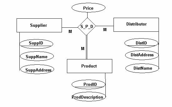
For one
instance of Supplier and one instance of Distributor there are many instances
of Product. For one instance of Supplier
and one instance of Product there are many instances of Distributor. For one instance of Product and one instance
of Distributor there are many instances of Supplier. A product is not considered if it is not
supplied by a Supplier to a Distributor.
A Supplier can exist without supplying to a Distributor, and a Distributor
can exist without receiving products from a Supplier.
The
corresponding tables in the relational model are:
S_P_D (SuppID, ProdID, DistID, Price)
Primary key (SuppID, ProdID, DistID)
Foreign key
SuppID references Supplier(SuppID)
Foreign key
ProdID references Product(ProdID)
Foreign key
DistID references Distributor(DistID)
Supplier(SuppID, SuppName,
SuppAddress)
Primary key
SuppID
Product(ProdID, ProdDescription)
Primary key
ProdID
Distributor(DistID, DistAddress,
DistName)
Primary key (DistID)